-40%
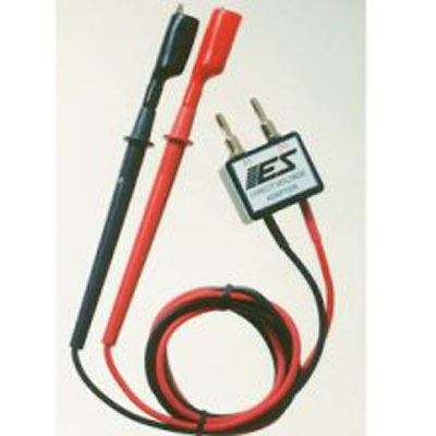
Logic Pulser Solder Kit Multi Testers Probes DTL/TTL Circuit Tester Test DC18V
$ 6.28
- Description
- Size Guide
Description
Store categorySign Up Now !
You may also like
Logic Pulser Solder Kit Multi Testers Probes DTL/TTL Circuit Tester Test DC18V
Product Description
100% Brand new and quality.
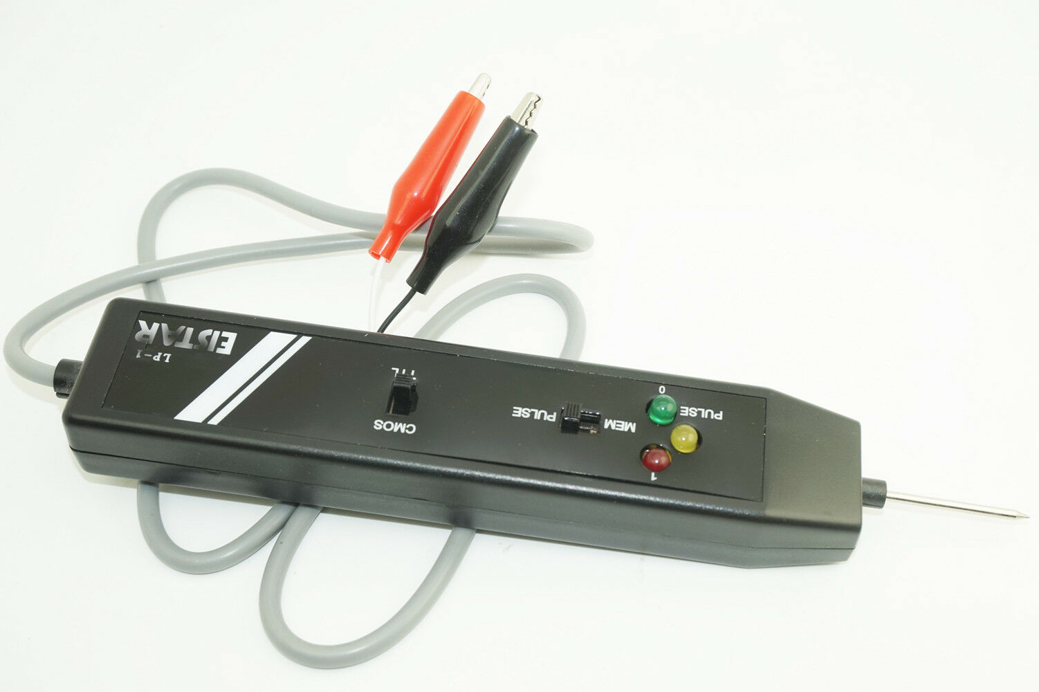
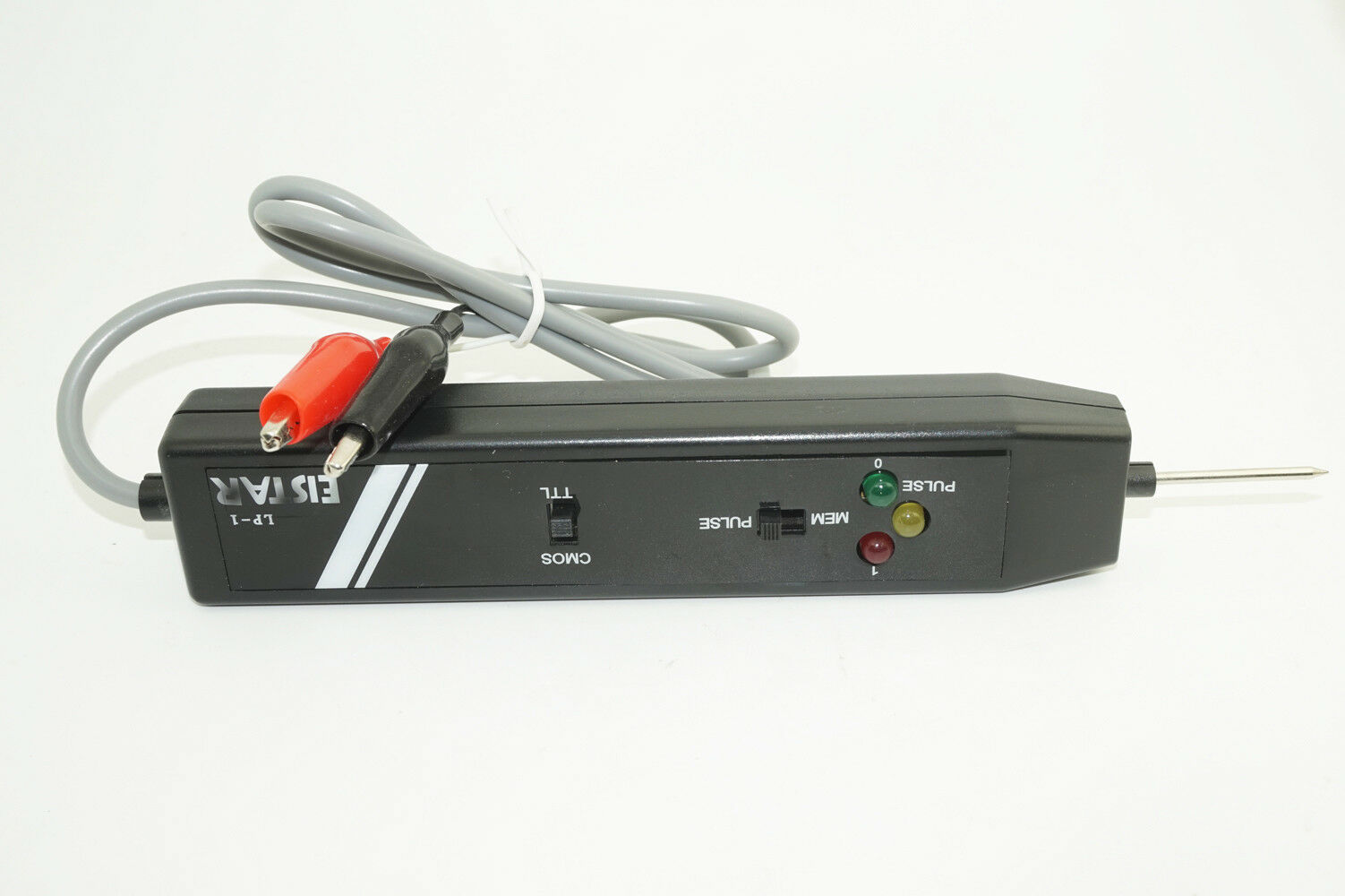
Connect RED clip to + terminal and BLACK clip to - terminal of the power source of the circuit under test. the supply voltage should not exceed 18v DC.
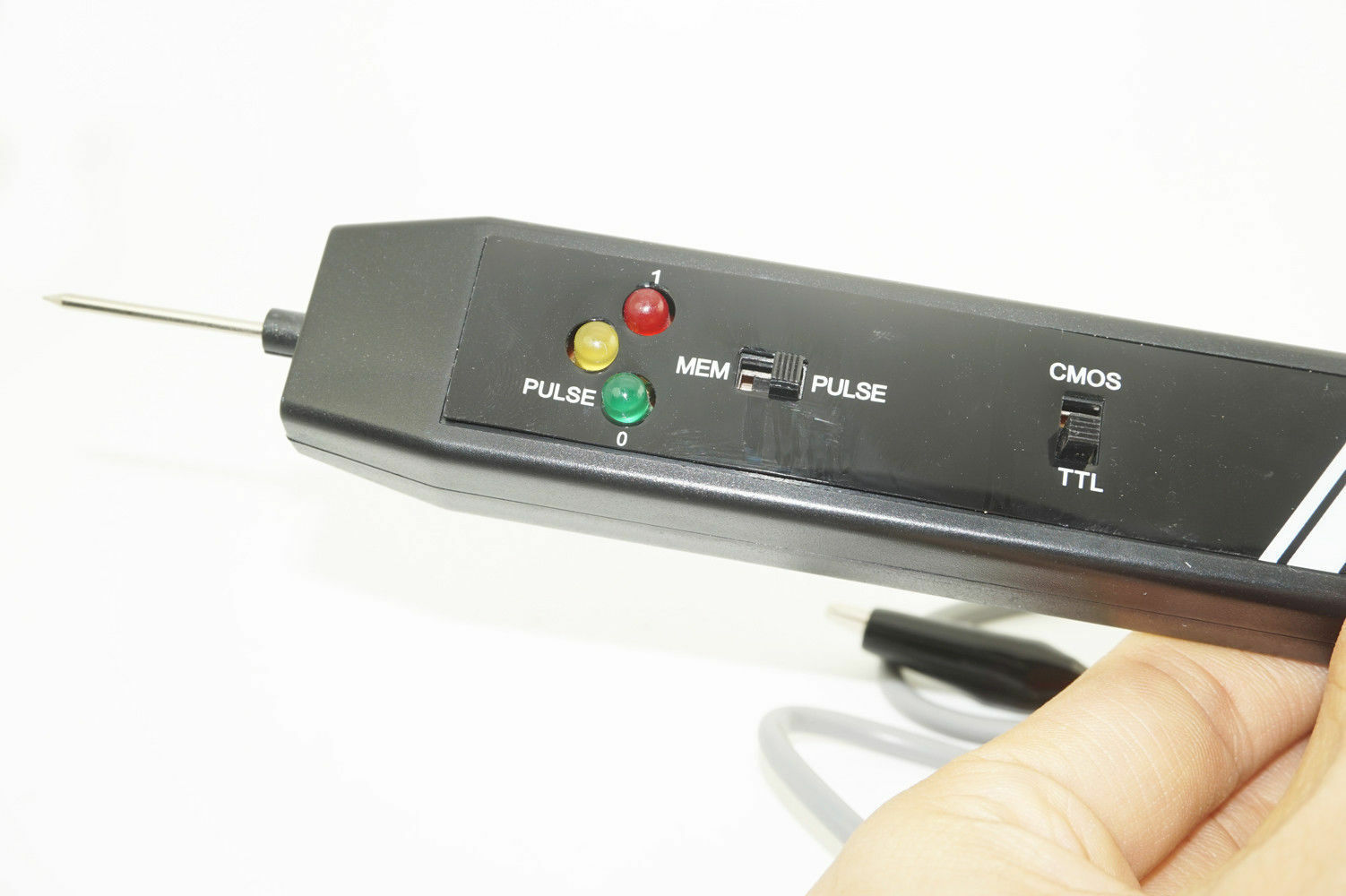
For TTL and DTL, set the upper select switch to the side marked "TTL". for COMS, set the upper select switch to the side marked "CMOS". contact the probe pin to the point to be tested, the LED's will indicate its logic states:
A: ALL LEDs OFF ---- HIGH IMPEDANCE
B: RED LED ON ------HIGH STATE [ 1 ]
C: GREEN LED ON --- LOW STATE [0 ]
D: ORANGE LED ON -- PULSE
For detecting and storing pulse or level transition set lower select switch to side marked " PULSE" first. contact the probe pin to the point to be tested. the LED's will indicate its basic state.
Then set the lower select switch to side marked " MEM", the orange LED will light when any pulse or level transition is detected. teh pulse direction, in comparison with the original basic state, can be determined. After use, reset logic probe by setting the lower select switch back to the side marked " PULSE"
Package included:
1x PROBE CIRCUIT TESTER
*Remarks: NOT include box or retail packing (Item will be wrapped safely in bubble envelop).
Payment Description
Returns & Feedback
Shipping & Handling
About us
Contact us
Payment Description
1. We accept payment via PAYPAL .
2. Payment must be made within 4 days of auction closing.
(Non-payment may result in a UPI (Unpaid Item) being put on your account. eBay will
automatically close your account if you accumulate 4 UPI's total.)
3. TOTAL AMOUNT DUE includes the final auction price plus S&H(Shipping and Handling).
4. S&H will be determined based upon the SHIP TO address.
PLEASE NOTE: S&H DOES NOT INCLUDE DUTIES, LOCATL TAXES OR ANY OTHER
IMPORTATION FEES.
5. Please list your special requests (color, packages, value of declaration, etc.) in the PAYPAL
NOTES SECTION when you make payment.
Returns & Feedback
YOUR SATISFACTION IS OUR FIRST PRIORITY!
We request that you contact us immediately before you take any action and feedback, so that we can satisfactorily address your concerns.
1. All items are brand new and have been passed the quality check. All are packed in a good condition before the item dispatches.
2. Please contact our Customer Services Executive before the item return.
3. Warranty: 30 days warranty from the dispatched date.
4. The item could be returned within the warranty period AND with the original package. Once the item return is required, our customer services executive will assist you to handle the return procedure.
5. Buyer is responsible for the shipping fee of the returned item.
Shipping & Handling
Delivery time:
By Airmail: Generally, about 7-15 business days to USA,
By Airmail: Generally, about 11-35 business days to UK, AU, America, West Europe, Asia;
Delivery to the rest of the world usually takes 21~35 working days;
We can also ship the item through express service like DHL, EMS, if you are ready to pay the extra charge. To know the details please contact us with email.
About us
We are always working hard for maintain high standards of excellence and strive for 100% customer satisfaction. So your positive feedback is very important. For any cases that you consider about the neutral and negative feedback, please contact our customer services executive for assistance. We will resolve your concern at your earliest convenience. Welcome you back to our store again.
Customer Service Executive Working Time(Beijing GMT+8 Time Zone)
Monday-Friday: 9:00-17:00
Saturday: 9:00-12:00
Sunday: out of office
Contact us
Feedback
Connect RED clip to + terminal and BLACK clip to - terminal of the power source of the circuit under test. the supply voltage should not exceed 18v DC. For TTL and DTL, set the upper select switch to the side marked "TTL". for COMS, set the upper select switch to the side marked "CMOS". contact the probe pin to the point to be tested, the LED's will indicate its logic states: A: ALL LEDs OFF ---- HIGH IMPEDANCE B: RED LED ON ------HIGH STATE [ 1 ] C: GREEN LED ON --- LOW STATE [0 ] D: ORANGE LED ON -- PULSE For detecting and storing pulse or level transition set lower select switch to side marked " PULSE" first. contact the probe pin to the point to be tested. the LED's will indicate its basic state. Then set the lower select switch to side marked " MEM",
